K6IF/W6BDN 40 Meter Rotatable Dipole
We designed and built this antenna to mount just below our tri-bander at about 70’ on a crank-up tower. It is an excellent all-around 40 meter antenna for those who don’t have room for (or can’t afford) a yagi, but want more than an inverted V. N6BT has done repeated tests that show that a flat-top dipole mounted at the same height as the apex of an inverted V is 1-2 S units (6-12 db) better than the V. This design is based on the idea that a rotatable dipole about the length of a 20 meter element is manageable by most hams with a tri-band yagi. The design goals were:
1) Reasonable cost
2) Acceptable mechanical bulk, measured by both weight and length
3) Simple enough construction to be a reasonable first non-wire home brew antenna project (as it was for us)
4) Good performance, preferably very close to that of a full-size 40 meter dipole
This design meets all of those goals. It is a bit mechanically fragile on the ground, but fine once it is in the air. It is possible to hold a run frequency from W6-land in Sweepstakes SSB using this antenna and 1500 watts – K6IF has done it J
This antenna is basically very simple, and quite easy to build. We strongly suggest that you read this entire article before doing any construction.
Start by constructing a 40’ long element from aluminum tubing. Actually, you want two 20’ element halves – there needs to be an insulator (installed later) in the middle for the feedpoint. We used 6063-T832 drawn seamless tubing from Texas Towers. The taper schedule is as below – or use your own. The only thing that matters (much, this is 40 meters after all, taper isn’t as critical to electrical length) is the length being right and the strength being suitable for your wind zone. I prefer to use rivets to assemble the element, but you can use screws or hose clamps as you prefer. An excellent source of rivets (and other hardware) is McMaster Carr. All lengths below are exposed lengths. The first three sections are double walled, so all 6’ of the 1” tubing has .875” tubing inside it, then there is another 3’ of .875” sticking out. Leave one joint, probably the .625” to .5” one, adjustable. If using rivets, this means drilling the holes from all three rivets, but only installing one. This picture is not to scale.
Now, build yourself two capacity hats. we built ours using .188” aluminum rod, again from Texas Towers. Use 8 spokes for the hat, each spoke 3’ long. Take 4 pieces of .188” rod, each piece 6’ long. Drill 4 7/32” holes spaced radially every 45 degrees and about ¼” apart in a 6” long piece of .625” tubing, and slide the rod into the holes. Braze the rods onto the tubing to form a hat that looked like this:
Finally, braze an aluminum perimeter wire (16 gauge is
fine) around the ends of the rods, so the hats looked like this:
For all of this brazing, use one of the low temperature (propane torch) aluminum brazing (or they might call it welding) rods available from your local welding supply store or home center. One example is DuraFix. Braze each rod onto the “hub” piece of .625” tubing, and braze (carefully) the wire onto the tip of each spoke. We found that the three tricks to using this technique successfully were:
1) Clean the rod and tubing carefully with the stainless wire brush. Take your time, and do it just before you are going to do the brazing, not a day or two before.
2) Be very careful to heat the work, and then rub or scratch the brazing rod against the work, rather than heating the rod. Do it using the same technique you would use to solder a good joint – you wouldn’t heat the solder, now would you? If you heat the brazing rod with the torch, it will melt, but it won’t stick to the work. You must scratch it against the heated work to get a good joint.
3) Practice. You can, and will, melt the .188” rod with the torch. Make up a practice piece of tubing, and braze at least 3-4 pieces of rod to it before you attempt your first real braze. Do all of the .188” rods before you attempt to braze the wire onto the perimeter – that is the trickiest work.
Next, assemble the element and feedpoint. Buy (or scrounge) a 12” piece of .75” o.d. fiberglass rod – you can get it from Tap Plastics, or from McMaster Carr. Put a mark at the center, and two inches to each side of the center. I prefer to use colored electrical tape for the two marks, one color for each half element. Cut two 6” long pieces of 1 ¼” grey UV resistant PVC pipe. Slit them the long way with a hacksaw, and then slide one piece onto the fat end of each element half. Slide them down until they are about 12” from the end.
Now slide the fiberglass rod into one element half until 4” is inside the tubing and 8” is exposed. Drill a 7/32” or ¼” hole through the tubing and the rod. Push a 2” long #10/24 stainless Philips head screw through the hole. Use a stainless steel Nyloc nut to secure the rod to the element. If you are using the colored tape trick, put a piece of tape on the element that is the same color as the tape mark on this side of the fiberglass rod. Now slide the other element half over the other end of the rod, again up to the mark that you made (so that 4” of the rod is inside the element half). Now drill a hole in line with the screw in the other element half, and put in another screw and Nyloc nut. Mark a witness mark on each element half and on the fiberglass rod, so that if you ever disassemble the antenna, you don’t have to guess how to put it back together. Now you have an element center that looks like this:
Finally, slide your pieces of PVC pipe down so that they rest up against the screws, and cover them over with electrical tape (to provide more UV protection). The PVC pipe will insulate the element from the U-Bolts that you will use to mount it to the mast to element plate – no necessary if you use a non-conducting material for the plate, of course. Now mount the hats on the ends of the elements, using rivets or whatever other technique you prefer. The .625” “hub” will slip over the end of the .5” tip sections of the element. Note: you may wish to drill the holes but wait to mount the hats until you are ready to raise the antenna. The element with the hats mounted is quite fragile and bulky.
For an element to mast plate, I prefer Premium Fiberglass Sheet from McMaster Carr. At 37,000 psi tensile strength, it is plenty tough. You can use ¼” for this application, although 3/8” or ½” will also work fine (it is just a bit more expensive). Garolite (also available from McMaster Carr) also works well, but is a even more expensive. If you are on budget, I have used ½” SeaBoard from Tap Plastics as well. It is a UV resistant high density plastic designed for marine applications, quite inexpensive, and will work for at least a while J Finally, many people use aluminum plate, which also works as long as you insulated the element with PVC pipe. No matter what you are going to use, cut yourself a piece 6” x 12” or so.
We use stainless u-bolts from DX Engineering – get two of the 1 ¼” size (or your favorite muffler clamp or other type of saddle clamp). Mark a 12” center line on your plate, then drill holes for the U-bolts about 1” from each end (so 10” apart). Your plate should look now like this:
Now mark a center line the short way, and drill holes for your mast mounting U-bolts placed so that their edges will be about ½” away from the edge of the plate. Again, we use the 2” saddle bolts from DX Engineering. Now your plate looks like this:
Now mount the element to the plate so that the two screws at the feedpoint are perpendicular to the plate, and mount your feedline and balun to the screws. Yes, you need a balun. If money is no object, use a Force 12 B1 balun or other similar bead type current balun. If money is tight, you can coil 12 turns of coax around a piece of 4” pvc pipe and then wrap the whole thing with electrical tape to UV protect it. If you haven’t already, mount the hats to the element, and raise the element. Now check the SWR. If the dip isn’t where you want it to be, lower the antenna (careful not to damage the hats), and adjust the length of each half of the element. Changing the length by three inches on each side will change the resonant frequency by 100 khz. Make the element longer to lower the frequency, shorter to raise the frequency. It is impossible for us to tell you exactly how long the antenna should be. Changing the height above ground by 20’ can have a big impact on your resonant frequency. 40’ should be close – you have to adjust you length for your installation – or model the antenna yourself at the height you plan to install it at. Either way, Your SWR curve should eventually look something like this:
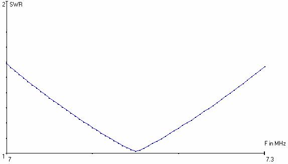
This antenna will have a feed impedance of almost exactly 50 ohms when mounted 70’ over average ground. Mounted 50’ up the impedance will rise to 70 ohms, but the SWR will still be under 2:1 for the entire band when fed directly with 50 ohm type coax.
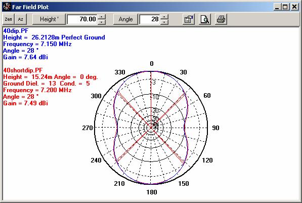
The gain of this shortened dipole is almost exactly that of a full size dipole, as is the pattern. The red line below is our 40’ long antenna, the blue line is a full size 40 meter dipole at the same height. As you can see, the pattern and gain are extremely close – our gain is down .15 dBi from the full size antenna.
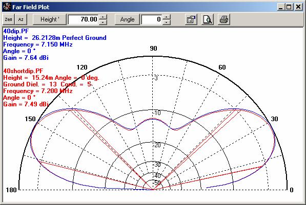
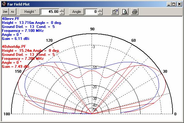
If w compare our short dipole to an inverted V with the apex at the same height, we see a small difference in performance of about 1.5 dBi. However, the dipole has much better low angle radiation performance than the V does. As I mentioned earlier, Tom Schiller has done real world tests that show that the actual difference is much larger than what NEC4WIN95 is telling us – possible due to the vertically polarized component of the inverted V’s radiation being counted at full value by the computer, but not in reality.

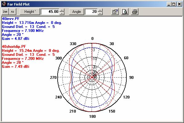
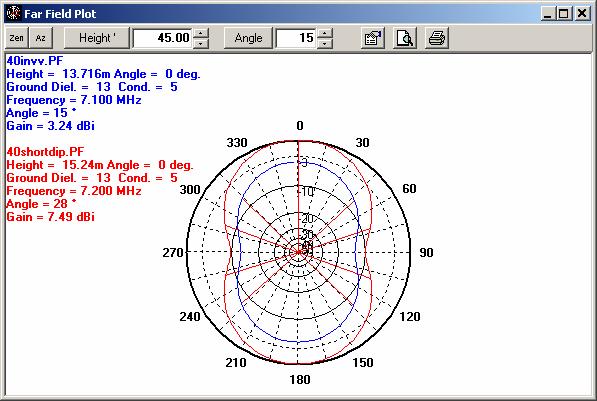
If we look at lower angles, we see the gap widen: at 20 degrees our dipole is almost 3 dBi better, and at 15 degrees it is about 3.25 dBi better – over half an S unit.
In summary, a 40’ long capacity hat’ed rotatable dipole for 40 meters can bring a new level of low band performance to the ‘average’ ham. It can be built for less than $100 from new parts in about one day. It offers performance very close to that of a full size dipole, despite being about 24’ shorter. It meets all of our design criteria, and performs well in real life too. What more can we ask for in an antenna design?