So now all I had to do was build 3 electrically identical antennas from 3 very different piles of aluminum. One antenna would be built completely out of parts from the old KLM 10 meter Big Sticker (the 'KLM taper'). One would have 5 elements and the boom from the Hy-Gain 105CA, with a driven element built from KLM stock out of Tom's garage (the 'Hy-Gain taper'). The last would use the 2" boom stock from the old 15 meter KLM out of Tom's garage, with 4 elements made from my old Gotham monobander and a driver and reflector made from old KLM stock (the 'mixed taper'). How hard could it be? (hi hi).
I started out with Nathan's published 24' boom 6 element 10 meter OWA design. The first thing that I did was verify that I could move the elements onto whole inch boundaries without breaking the antenna. The original reflector-driver spacing was 43.86", I moved it to 44", and so on. This had no discernible effect on the antenna as modeled on the computer, and made the antennas easier to build. Since I didn't really know how to retaper the elements, I did it brute force. I created a model in NEC4WIN95 for each individual element of the antenna with the original taper. I used these to model the impedance and resonance of each element. Then I build models of each element in each of the 3 taper schedules that I had aluminum for. I tuned each of those elements until their resonance matched the original taper. Then I 'assembled' these individual elements back into complete antennas, and tuned the models.
I ended up with 3 models, each electrically very similar, but mechanically very different. Here is the YW plot for the KLM taper antenna, the other two are basically the same.
Then I had to sort out all the other mechanical issues of building and mounting the antennas.
 For the construction,
I decided to use 1/4" thick Seaboard
for the boom to element plates. Seaboard is a marine grade of high
density polyethylene. It is quite strong, although flexible.
It has good outdoor survivability, and machines easily. I wanted
to use Garolite, which W3LPL and others have used with great success, but
the stuff is too expensive. When you are building 18 elements worth
of antennas, the cost really adds up. McMaster
Carr gets north of $25/ft for grade LE Garolite. For 3" x 6"
plates, I was going to need $75 worth of Garolite, plus I would have to
pay shipping, tax, and cut the plates and drill all the holes myself.
I just wasn't ready to spend that much on hardware for temporary antennas,
and time was short. I had the Seaboard cut and drilled for me by
Tap
Plastics, and the whole job cost less than the raw Garolite would have
cost.
For the construction,
I decided to use 1/4" thick Seaboard
for the boom to element plates. Seaboard is a marine grade of high
density polyethylene. It is quite strong, although flexible.
It has good outdoor survivability, and machines easily. I wanted
to use Garolite, which W3LPL and others have used with great success, but
the stuff is too expensive. When you are building 18 elements worth
of antennas, the cost really adds up. McMaster
Carr gets north of $25/ft for grade LE Garolite. For 3" x 6"
plates, I was going to need $75 worth of Garolite, plus I would have to
pay shipping, tax, and cut the plates and drill all the holes myself.
I just wasn't ready to spend that much on hardware for temporary antennas,
and time was short. I had the Seaboard cut and drilled for me by
Tap
Plastics, and the whole job cost less than the raw Garolite would have
cost.
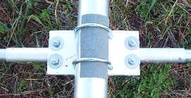
The next question was hardware. Again, price drove the decision. Since these antennas were only going to be up for a short while, I couldn't bring myself to spend the money on stainless hardware. I ended up buying zinc plated steel u-bolts, but using stainless fender washers (1" o.d., to keep the stress on the plastic down) and nuts. I also put a small sheet of 3M non-slip tape on the boom. I didn't want to crank down too hard on the u-bolts, to avoid breaking the plastic, so I hoped that the non-slip tape would help hold the elements in place. Finally, I used rivets to assemble the elements. I find aluminum rivets easy and quick to use, and very secure.
 The construction
went smoothly, on the whole. It took me and Tom working together
about 3 hours to build each antenna. First measuring the boom and
marking the element locations, then mounting the boom to element plates
onto the boom. Then we assembled the elements (we used foaming
refrigerator coil cleaner from Grainger
to clean the aluminum. It worked wonderfully, and was very fast.
But the stuff has hydrofluoric acid in it, which is very very nasty - so
extreme care was required), and mounted them onto the boom. Then
we checked the length of each element to be sure.
The construction
went smoothly, on the whole. It took me and Tom working together
about 3 hours to build each antenna. First measuring the boom and
marking the element locations, then mounting the boom to element plates
onto the boom. Then we assembled the elements (we used foaming
refrigerator coil cleaner from Grainger
to clean the aluminum. It worked wonderfully, and was very fast.
But the stuff has hydrofluoric acid in it, which is very very nasty - so
extreme care was required), and mounted them onto the boom. Then
we checked the length of each element to be sure.
When they were all built, I hoisted each antenna up to about 12' on a rope hung from a tree branch, and they all looked basically ok on my MFJ. One, the Hy-Gain taper, was perfect. The other two looked a bit odd, but had a definite dip in the middle of the band. I decided to go for it (stupid, but I was in a hurry), and the KLM taper antenna went up on the tower on November 22nd. A quick check with the 259B showed that the antenna was about 1.7:1 at 28.4, vs. a design of 1.2:1, and dipped to 1.5:1 at 28.8, vs. a design of <1.1:1. The feed impedance peaked at 33 ohms vs. a design of 53 ohms. Something was wrong.
Back to the drawing board. I sent out an email to Tower Talk and to W4RNL asking for help. I got lots of good replies. But the bottom line was that my computer models didn't match the real antennas. I wasn't sure I could fix them if I didn't know why or how they were broken. I spent a few hours trying to break the models - making elements longer and shorter, playing the spacings, trying to replicate on the computer the behavior of the actual KLM antenna. I failed miserably. I also modeled the antenna using YagiMax (shareware) and the YW program from the ARRL Antenna Book, but neither gave better results. The one thing that I did convince myself of was that I could play around with the driven element and first director quite a bit without effecting the gain much. That gave me some confidence.
At this point, I was not a happy camper. It was Thanksgiving weekend, 2 weeks before the contest. I could leave the KLM up, and live with the power imbalance caused by the 1.7:1 SWR (vs. the lower SWR on the other antennas), but I wanted to fix it. I just didn't know how. I finally decided to head back up to Tom's and take a closer look at the other two antennas (that were still on the ground). I raised them up to 10' on the side of the tower, and compared the readings to the antennas resting on the saw horses. It was clear that although the readings were different, I could probably tune the antennas on the horses with good results. It also became clear that while the Hy-Gain taper antenna was fine, the mixed taper antenna had similar problems to the KLM. I decided to use it as a guinea pig - if I could fix it then I would lower the KLM and try to fix that one too.
Luckily, it didn't take long to fix the mixed taper antenna. I moved the first director in about 2 inches (closer to the DE). That raised the feed impedance a bit. Then I lengthened the first director about an inch on each side. That raised the impedance more. Than I shortened the driven element by about an inch on each side, and that canceled out the reactance. Now the mixed antenna is 1.3:1 at 28.4 and 1.2:1 at 28.8 - plenty good enough.
That brings us up to real time on this part of the story. I am writing this on Tuesday, November 28th - C minus 10 days. The KLM is still broken and on the tower, I plan to lower and fix it Friday. The other two antennas are on the ground, tuned, riveted and ready to go. I plan to raise them into place either Friday or early next week (after I lower and raise the KLM).
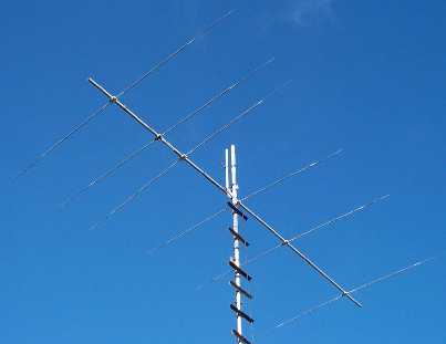
A word at this point on my plans for mounting the antennas. As you can see in the picture above, the top antenna (the KLM taper) will be mounted near the top of the mast. The mast is turned by a prop pitch rotor, and with the tower raised that antenna will be at about 85'. Tom had ordered a TIC Ring Rotor that will turn a C-31XR next year, and it arrived a couple of weeks ago. The middle antenna will be mounted on the Ring at the top of the 3rd section of the tower, at about 55'. The bottom antenna I plan to mount on a steel plate welded onto a rod that fits into the top of the lower section - it will be at about 25'. The bottom antenna will be fixed in place by a rope and aimed at the U.S.
So here is a brief list of what I have to do in the next 10 days: